Harris Aerial Support
Battery and Power
General Information based on Drone model
H6 Models:
H6 Electric: Charging
The H6 platform is made to accommodate two separate battery configurations depending on the power format being used. For H6 electrics, the recessed bay on top of the frame allows for 12S battery packs to be quickly swapped in the field. The H6 Hybrid (EFI and Hydrone) use two 6S batteries mounted underneath the frame to provide power to the conversion system for startup and act as a backup in the event of fuel depletion or converter failure.
H6 Electric: Charging
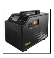
For charging and discharging, the Tattu TA3000 or Tattu TA3200 require four cables total. Connect both the AS150U charging cables and Molex balance cables to the charger, and then connect each battery to the charger. To charge select “Charge” mode by using the lower button, and hold the right button to “Start”. For storing batteries, select “Storage” mode by using the lower button, and hold the right button to “Start”. It is recommended to charge at a rate of 16A or less at all times to prevent overcharging. Note that charging at a lower rate can extend your batteries lifetime.
Important: Tattu chargers are designed to intelligently regulate power delivery when charging batteries with a 110VAC or 220VAC circuit. In the event field charging is being performed using a generator and inverter, verify that you are providing the charger adequate wattage.
H6 EFI & Hydrone: Charging
H6 EFI & Hydrone: Charging
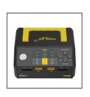
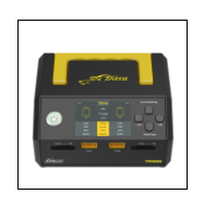
For charging and discharging, the Tattu TA1000 only requires connecting the battery and its balance leads, and selecting either the “Charge” or “Storage” button on the front panel.
General Battery Information based on drone model:
H6HL
H6HL: Charging
The H6HL platform is made to accommodate a total of eight batteries to allow for extended flight times while providing the largest payload capabilities out of all the HA platforms. H6HL’s have a recessed bay on top of the frame that allows for a total of four 6S battery packs to be quickly swapped in the field using a specially designed aluminum box for securing each battery and its balanced leads. Additionally, the H6HL has four aluminum trays mounted underneath the frame that allow for four additional 6S battery packs. These trays are easily removable by disengaging a lever allowing each tray to slide out with ease.
H6HL: Charging
For charging and discharging, the Tattu TA1000 only requires connecting the battery and its balance leads, and selecting either the “Charge” or “Storage” button on the front panel.
Battery Charger Types
Charger Types:
Hx8 Electric: Charging

The Hx8 platform is made to accommodate two separate battery configurations dependent on the power format being used. For standard Hx8 Octocopters, the recessed bay on top of the frame allows for 12S battery packs to be quickly swapped in the field. The Hx8 Tether uses two 6S batteries mounted underneath the canopy to provide power to a conversion system for startup, and act as a backup in the event of converter failure.
H8 Octocopter: Charging
For charging and discharging, the Tattu TA3000 or Tattu TA3200 require four cables total. Connect both the AS150U charging cables and Molex balance cables to the charger, and then connect each battery to the charger. To charge select “Charge” mode by using the lower button, and hold the right button to “Start”. For storing batteries, select “Storage” mode by using the lower button, and hold the right button to “Start”. It is recommended to charge at a rate of 16A or less at all times to prevent overcharging. Note that charging at a lower rate can extend your batteries lifetime.
Important: Tattu chargers are designed to intelligently regulate power delivery when charging batteries with a 110VAC or 220VAC circuit. In the event field charging is being performed using a generator and inverter, verify that you are providing the charger adequate wattage.
Hx8 Electric + Tether: Charging
H8 Octocopter + Tether: Charging
For charging and discharging, the Tattu TA1000 only requires connecting the battery and its balance leads, and selecting either the “Charge” or “Storage” button on the front panel.
Battery Safety
Safety Protcols
Powered Format Swaps
- Do not plug 12S and 6S batteries simultaneously. When swapping from EFI to electric, designate a specific battery for the build to avoid cross-contamination.
- Do not mix battery types while charging or in use. For the H6HL, avoid using 12S batteries. Always perform a full storage charge if the drone will not be used for an extended period to maintain battery health.
Battery Incompatibility
Never plug 6S or 12S batteries into battery receptacles not designed for their intended use.
E.g. – The H6 EFI & Hydrone XT90 connectors are designed for 6S batteries only. This harness combines two 6S 4750mAh batteries in series to create a nominal voltage potential of 44.4V (22.2V each) that powers the generator and your vehicle. Using two 12S batteries improperly with these connections creates a nominal voltage potential of 88.8V and will severely damage the electronics in your vehicle.
E.g. – The H6HL uses eight AS150U connections to utilize voltage potential from eight individual batteries. These batteries are 6S 30000mAh batteries with a nominal voltage potential of 22.2V each. Do not confuse them with 12S batteries despite them using an AS150U connection. Each harness on the H6HL pairs two batteries in series to create a nominal voltage potential of 44.4V. This creates a total of four 44.4V voltage sources each in parallel to one another to extend flight time. Using two 12S batteries improperly with these connections creates a nominal voltage potential of 88.8V and will severely damage the electronics in your vehicle.
E.g. – In other cases such as inserting 6S batteries into connectors designated for 12S batteries, damage is unlikely to occur, however each battery would then be in parallel to one another, resulting in a total nominal voltage potential of 22.2V. This will not be enough to power the systems onboard your vehicle effectively. Always use 6S and 12S batteries where specified.
Battery Safety
Safety Protcols
Submit A Ticket
Contact Information
Drop us a line here and we will get back to you within 24 hours.
- +1-850-800-9103
- support@harrisaerial.com
Maintenance information based on battery model
Maintenance Protocols:
Visual Inspection
Inspect the battery casing for bloating or physical damage. Inspect positive and negative leads for kinks, gouges, or charring near the connectors. Inspect the integrity of the balance leads wires, pins, and connector.
Battery Heath Inspection
Use a Capacity Controller device or your charger to inspect the voltage of each cell. At maximum charge ~25.2V, each cell (6 cells) should have a voltage of around 4.2V, at storage charge ~22.2V, each cell should have a voltage of around 3.7V. Between each cell there should not be any difference greater than 200mV/0.2V. If there is, verify that the battery was properly balanced charged, if this does not resolve the imbalance this indicates the cell is beginning to die. If a cell shows a significant difference in voltage or lack thereof, discontinue using this battery and dispose of according to your local ordinance.
Storage Instructions
When batteries are not in use or being stored for long periods of time, it’s critical for both the health of the battery and safety of your crew/facility that batteries are storage charged. Batteries can either be depleted during a mission or by using your charging and selecting “Storage” mode. |
Replacement Recommendations
Damaged, bloated, or any battery otherwise exhibiting symptoms of unexpected operation is an extreme fire and explosion hazard. It is important to perform regular inspections of your batteries to prevent hazards.
Replacement of batteries is recommended either when the batteries have been used for 150 hours of flight, have dead cells, or are damaged. If you suspect your battery is damaged and not operating properly or exhibiting end-of-life symptoms due to bloating, damage, or bad cells, temporarily contain the battery in a firesafe battery container until it can be disposed of in accordance with your local laws and regulations.
Maintenance information based on battery model
Maintenance Protocols:
Visual Inspection
Inspect the battery casing and plug for physical damage. Verify that battery voltage LED indicators display the correct voltage (each LED = 25% charge). Verify there are no battery LED codes present.
Battery Heath Inspection
Use your Tattu charger or the Tattu mobile app to inspect 12S Smart batteries and cells. Both offer analytics on the health, error codes, and other important data regarding your battery. The mobile app can be downloaded via your phones app store and uses bluetooth to connect to each battery according to its serial number (GD0######). At maximum charge ~50.4V, each cell (12 cells) should have a voltage of around 4.2V, at storage charge ~44.4V, each cell should have a voltage of around 3.7V. Between each cell there should not be any difference greater than 200mV/0.2V. If there is, verify that the battery was properly balanced charged, if this does not resolve the imbalance this indicates the cell is beginning to die. If a cell shows a significant difference in voltage or lack thereof, discontinue using this battery and dispose of according to your local ordinance.
Storage Instructions
When batteries are not in use or being stored for long periods of time, it’s critical for both the health of the battery and safety of your crew/facility that batteries are storage charged. Batteries can either be depleted during a mission or by using your charging and selecting “Storage” mode. |
Replacement Recommendations
Damaged, bloated, or any battery otherwise exhibiting symptoms of unexpected operation is an extreme fire and explosion hazard. It is important to perform regular inspections of your batteries to prevent hazards.
Replacement of batteries is recommended either when the batteries have been used for 150 hours of flight, have dead cells, or are damaged. If you suspect your battery is damaged and not operating properly or exhibiting end-of-life symptoms due to bloating, damage, or bad cells, temporarily contain the battery in a firesafe battery container until it can be disposed of in accordance with your local laws and regulations.
general warranty information
Warranty Conditions & Compliance Checks
Compliance
Compliance with recommended maintenance schedules is essential to maintain the warranty. Any damage resulting from improper maintenance, unauthorized repairs, or the use of non-approved components will void the warranty.
Voided Warranty Conditions
- Unauthorized modifications or repairs.
- Use of non-approved batteries or chargers.
- Failure to adhere to recommended inspection and maintenance schedules.
- Operating the drone outside of specified environmental conditions.
- Any damage resulting from crashes or improper handling.
Our team will verify all warranty claims & conditions onsite to ensure their accuracy. If we discover any data or evidence that indicates deception or improper usage – it will void your warranty.
general warranty information
Warranty Conditions & Compliance Checks
TATTU App - QR Code For App Store

general warranty information
Warranty Conditions & Compliance Checks
Submit A Ticket
Contact Information
Drop us a line here and we will get back to you within 24 hours.
- +1-850-800-9103
- support@harrisaerial.com
Generator Maintenance
Fueling Information
H6 EFI: Fueling
H6 EFI: Fueling
Warning: Please use caution when refueling your aircraft. Never fuel your aircraft while it is powered on. Removing batteries while fueling is recommended as fuel spillage or gas leaks could result in a fire or explosion leading to serious injury or death.
H6 EFI:
- Use only 93 octane (ethanol-free preferred) or higher fuel mixed with smokeless 2-cycle oil at a ratio of 25:1.
- Remove the fuel cap and begin filling the tank. Note: The amount of fuel can be measured (in liters) using the fill indicators inside the tank.
- Replace the fuel cap, clean any spills, and inspect the tank for leaks.
- Remove the small clear fuel line from the fuel injector at the bottom of the generator. Use a purge bulb to draw fuel from the tank into the line until there are no air bubbles present. Re-insert the fuel line onto the injector.
Tip: Don’t forget to set the fuel level in HA Ground Control (page 35).

H6 Hydrone: Fueling
H6 Hydrone: Fueling
Warning: Fueling the H6 Hydrone requires proper training and is not referenced in this document. Do not attempt to refuel your hydrogen tank without proper training or while it is powered.
Reference: Fueling instructions are referenced in a document titled, “Refilling Hydrogen Tanks – Version 1.01”. Please contact support@harrisaerial for this procedure.
Pre-Flight Checks (Prior To Each Flight)
Fuel Tank and Fuel Line Inspection
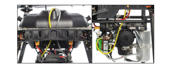
Trained personnel should inspect the fuel tank and all fuel lines. When inspecting the fuel tank verify that the fuel cap and vent plug are functional and look for signs of deformation, fuel permeation, or leaking each of which could indicate a faulty fuel tank and require a replacement. When inspecting the fuel lines start from inside the fuel tank working in the direction of the generator. Check the integrity of each fuel line, this could include but is not limited to: strong connections at each brass L-pipe, strong connections at the generator, no line has any damage (kinking, pulling, or gouges) resulting in a loss of fuel flow.
Hydrogen Tank and Gas Line Inspection
In addition to the procedures listed in Section 1.1, trained personnel should inspect the fuel tank and all fuel lines. When inspecting the hydrogen tank and gas line make sure there are no leaks at the regulator or along the gas tubing, a hissing sound may be present if the tank is full and a leak has occurred. If a leak at the regulator or gas lines is suspected, a replacement will be required.
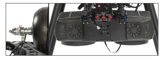
Generator Inspection
Generator Inspection
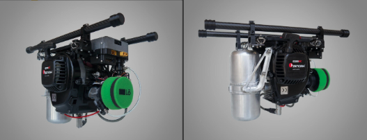
In addition to the procedures listed in Section 1.1, trained personnel should inspect the I/O wiring, telemetry cable, air filter, pulley, spark plug boot, and braided dampeners.
- I/O wiring (input/output) installation should be verified before every flight if for any reason the generator or its wiring has been removed recently. Each I/O cable is labeled with a descriptive sleeve, ie; “Battery 12S” or “Output→PDB”. When looking at the aircraft from the rear, the “Battery 12S” cables XT90 Male connector should be inserted into the center right XT90 connector on the bottom frame plate, and its opposite end, the XT90 Female connector, should be connected to the sunken connector on the generator. Likewise, the “Output→PDB” cables XT90 Female connector should be inserted into the center left XT90 Male on the bottom frame plate, and its opposite end, the XT90 Male connector, should be connected to the protruding connector on the generator.
- The telemetry cable has two ends, one with a five pin connector and the opposite a three pin connector. Ensure both ends are securely fastened to their respective ports: five pin → governor board, three pin → telemetry port (at the rear of Flight Control Box).
- Inspect the air filter and verify that it is free of excess debris or residue from fuel or oil. Ensure the air filter is securely placed on the intake with the air temperature sensor snug between both.
- Inspect the crank pulley and verify there is an ease of motion and there is seizure of the pulley system.
- Verify the spark plug boot is fully seated.
- Visually inspect each braided damper, when the generator is installed correctly onto the payload rails, the dampers should be centered and not pulling in any given direction. If there are any signs of pull this could damage the dampers.
5 Hour Generator Maintenance
This section details generator maintenance intended as a five hour maintenance item that should be performed at or before every 5 hours of flight —
Performing routine checks on the fuel, air, and spark systems relative to EFI powered aircraft is recommended for maintaining the optimal performance expected from HA-EFI equipped UAS. This inspection should include a visual inspection of the fuel filter and fuel line integrity, the air filter cleanliness and integrity, and the spark plug integrity.
Fuel Filter and Fuel Line Integrity Inspection
Begin by removing the fuel line grommet located at the top of the fuel tank, and pull the fuel filter through the internal baffles. Inspect the wool filter making sure it is secure in its fuel line and check for debris or buildup that would otherwise obstruct the flow of fuel and remove it if possible. If removal of debris or buildup is not possible, replacement of the filter is recommended. Proceed to inspecting the fuel lines at both the fuel tank and generator and look for kinking, pulling, gouges, or possible thinning on any part of the line. If degradation or damage of any fuel line is suspected, replacement of the entire fuel line system is recommended
Air Filter Inspection
Remove the air filter from the intake and throttle body of the generator. Inspect the air filter rubber interface to make sure it grasps the intake firmly and check the interior and exterior foam of the air filter for debris or buildup (which could consist of carbon deposits from exhaust, oil or gasoline spills, or environmental fallout) that could obstruct airflow and remove it if possible. If removal of debris or buildup is not possible, replacement of the air filter is recommended.
Spark Plug Inspection
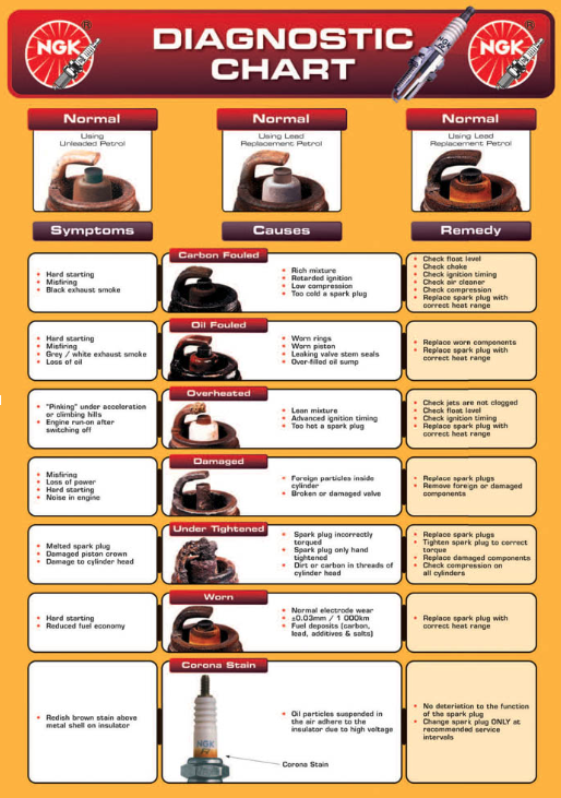
If generator performance is in question, remove the spark plug boot, located at the bottom of the generator to reveal the spark plug. Using the included spark plug wrench, remove the spark plug and inspect the electrode. Look for degradation of the center electrode or side electrode, and any carbon deposits that may be present. If carbon deposits are present but minor in nature, carburetor cleaner or isopropyl alcohol may be used to remove deposits. For uncertainties, refer to the chart on the next page.
The provided NGK manufacturer diagnostic chart is useful in determining how your generator is running, and some of possible causes for fouling and their remedies.

25 Hour Generator Maintenance
This section details generator maintenance intended as a twenty-five hour maintenance item that should be performed at or before every 25 hours of flight—
To achieve the longest life from any engine, preventative maintenance is necessary to ensure the mechanical and electrical systems that it is composed of operate as efficiently as possible or are otherwise replaced. This section will provide detailed instructions for removal and replacement of the following Löweheiser components: air filter, fuel filter, fuel lines, spark plug, and braided wire dampers (if necessary).
Air Filter Replacement
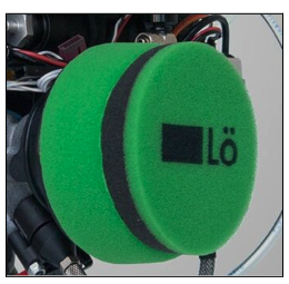
Air Filters prevent any contaminants or environmental fallout from getting into the combustion chamber that would otherwise cause a poor ignition cycle. As a result, over time these filters will lose their ability to properly intake air, and should be replaced every twenty-five hours of flight. To replace, simply pull the air filter off the intake, and place another in its place while ensuring the air temperature sensor is placed between the filter and intake during installation.
Fuel Filter Replacement
Begin by removing the fuel line grommet located at the top of the fuel tank, and pull the fuel filter through the internal baffles. Firmly grasp the filter with one hand, while grasping the attached fuel line close to the nipple of the filter, and pull the fuel line off. If the fuel line is difficult to remove, cut the fuel line as close to the filter as possible, and use a razor knife to carefully score and remove the remaining fuel line. Before installing a new fuel filter, make sure the nipple is clear of any previous fuel line or material, and that the fuel line to be mated with the fuel filter has been trimmed flush.
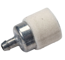
Fuel Line Replacement
Begin by removing the fuel line grommet located at the top of the fuel tank, and pull the fuel filter through the internal baffles. Remove each fuel line from its respective brass-L pipe for both the internal and external fuel lines. Remove the large clear and large yellow fuel line from the generator taking note of which nipple they mate to. If any fuel line is difficult to remove, cut the fuel line as close to the nipple as possible, and use a razor knife to carefully score and remove the remaining fuel line. Lay out each fuel line and measure the length of each segment. Prepare fresh fuel lines using these measurements making sure the end of each line is trimmed flush. Insert each new fuel line in place of the pre-existing fuel line.
Spark Plug Replacement
Begin by removing the spark plug boot, located at the bottom of the generator. Using the spark plug removal wrench, loosen the spark plug and remove by hand being careful not to break the spark plug upon exit. Replace the spark plug with a new NGK-CMR7H, inserting the spark plug into the ignition chamber and tightening until snug. Be careful not to overtighten the new spark plug as this may result in fracturing and poor spark while running.
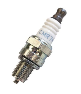
Braided Wire Damper Replacement
Inspect each braided damper around the generator mounting clamps, if any braided steel damper exhibits signs of wear or fraying, replacement if required. To remove a damper, loosen both the top and bottom retaining screws with a 2.5mm hex allen wrench and remove the faulty damper. Replace with a new braided damper, and insert two new screws with blue loctite. Repeat this procedure for all damaged braided steel dampers.
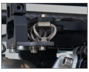
75 Hour Generator Maintenance
Harris Aerial Löweheiser EFI Recommended Annual Maintenance | ||
| ||
Service or Part | Service Interval | Estimated Cost (Prices subject to change) |
Service/Maintenance labor hour *When sent to our facility for generator maintenance (includes bench testing / diagnostic) | As Needed | $250/hr |
Fuel Line Replacement Kit (All sizes) | 25 Hours / As Needed | $40/kit |
Fuel Line Fittings / Gaskets Kit | As Needed | $60/kit |
Braided Steel Wire Dampeners (x8 per kit) | As Needed | $200/kit |
Throttle Position Sensor and Servo Control | 75 Hours | $250 |
Fuel Pump | 75 Hours | $300 |
Fuel Regulator | As Needed | $300 |
300 Hour Generator Maintenance
Over time, the integrity of the generator’s cylinder, piston, and seals will degrade and when this occurs a lack of compression may occur. As a result, the Löweheiser EFI generator has a recommended replacement lifetime of three-hundred hours. This is to ensure that both the generator and aircraft function and operate at their optimal performance. Similarly, Intelligent Energy fuel cells are subject to a degradation in performance over many hours, and thus, replacement is required after three-hundred hours.
Generator Removal and Installation
To remove a Löweheiser EFI generator, first remove the large clear and large yellow fuel lines from the fuel inlet and fuel return, unplug the telemetry cable which is inserted into the flight control box, and remove the four M3x8 socket screws located on each rail clamp. Be sure to support the generator while removing these screws, otherwise the generator may fall during removal. Use the same process detailed here, but in reverse order for replacement generators. Refer to Appendix A for torque specifications.
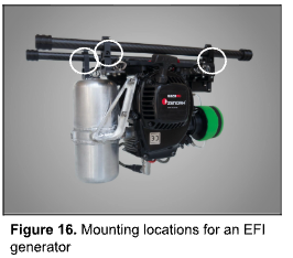
Fuel Cell Removal and Installation
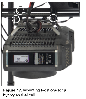
To remove an Intelligent Energy fuel cell, first make sure to remove any gas lines that may still be connected to a hydrogen tank, unplug the telemetry cable which is inserted into the flight control box, and remove the four M3x8 socket screws located on each rail clamp. Be sure to support the generator while removing these screws, otherwise the generator may fall during removal. Use the same process detailed here, but in reverse order for replacement generators. Refer to Appendix A for torque specifications.
general warranty information
Warranty Conditions & Compliance Checks
Compliance
Compliance with recommended maintenance schedules is essential to maintain the warranty. Any damage resulting from improper maintenance, unauthorized repairs, or the use of non-approved components will void the warranty.
Voided Warranty Conditions
- Unauthorized modifications or repairs.
- Use of non-approved batteries or chargers.
- Failure to adhere to recommended inspection and maintenance schedules.
- Operating the drone outside of specified environmental conditions.
- Any damage resulting from crashes or improper handling.
Our team will verify all warranty claims & conditions onsite to ensure their accuracy. If we discover any data or evidence that indicates deception or improper usage – it will void your warranty.
general warranty information
Warranty Conditions & Compliance Checks
Submit A Ticket
Contact Information
Drop us a line here and we will get back to you within 24 hours.
- +1-850-800-9103
- support@harrisaerial.com
Battery & Power
Additional Charger Information
Tattu User Manual TA1000:
- Compatibility: Specific to 6S batteries.
- Features: Designed for high-capacity, high-performance batteries, providing safe and efficient charging.
Download the Tattu TA1000 User manual HERE
Tattu User Manual TA3200/3200HV:
- Compatibility: Specific to 12S batteries.
- Features: Designed for high-capacity, high-performance batteries, providing safe and efficient charging.
Download the Tattu TA3200/3200HV User manual HERE
Battery & Power
Ticket Submission
Submit A Ticket
Contact Information
Drop us a line here and we will get back to you within 24 hours.
- +1-850-800-9103
- support@harrisaerial.com