Harris Aerial Support
Connection & Integration
initial setup guide
Complete Checklist:
Connecting To The Aircraft: Ground Control Station (C-GCS)
Get to know your GCS specs below and follow along with our visual guides:


Connecting To The Aircraft: Troubleshooting (C-GCS)
CONNECTION TROUBLESHOOTING
- Connection issues are typically related to one or more of the following factors: hardware, software, or interference. In this section we’ll cover possible issues and potential solutions.
- RC Failsafe:
If an RC failsafe is experienced, specifically when the aircraft has not been flown BVLOS, behind an obstruction, or is close in proximity to your launchsite, there is a possibility that either the antennas, coaxial cables, or radio is damaged and has a weak received signal-strength (RSSI). Allow the vehicle to RTL and once a connection is reestablished, attempt to replicate the issue. Please refer to the “Radios” section on this page for more information about radio troubleshooting.
If an RC failsafe is experienced while the vehicle is at range or BVLOS this may be due to a brief loss of connection. Allow the vehicle to RTL or establish manual control once the vehicle is within VLOS to determine if connection has been reestablished.
- Unable to connect to vehicle:
Make sure the radio (RF Design or Microhard) is powered on by checking the radios status LEDs. If no LEDs are present, flip the radio power switch to “on”. Radio(s) and power switch(es) can be found beneath the keyboard.
- RFD 900MHz radios when transmitting and receiving, will exhibit rapid blinking in intermittent patterns from the rear left of the radio mount/enclosure.
If the RFD radios LED is off or blinking in a slow steady pattern it indicates that there is no data being received. Please refer to the “Radios” section on this page for more information about radio troubleshooting.
- Microhard 2.4 GHz radios have three status LEDs in sequential order, when transmitting and receiving, will exhibit rapid blinking in intermittent patterns.
If the Microhard radios LEDs are blinking in a sequential pattern from side to side it indicates there is no connection to the air unit. Please refer to the “Radios” section on this page for more information about radio troubleshooting.
Loss of Video Stream (FPV):
- If a loss in your first-person view (FPV) camera’s video stream occurs, the first step is determine which radio your aircraft is equipped with, Herelink or Microhard.
- Herelink equipped vehicles use a CamPark FPV camera which streams video through a mini HDMI cable. This is then transmitted to a Herelink controller specifically for viewing the video feed.
If video streaming is not present, start by power cycling the CamPark FPV camera and removing the HDMI cable from the side of the camera.
Once the camera has powered back on, remove it from its mount and enter the settings menu – press the menu button on the front until settings appears, navigate through the menu and locate both screen saver and power saver menus, change these to “OFF”. Reinsert the HDMI cable and check your Herelink for video stream.
If video streaming issues persist, check the HDMI channel on HAGC – In the bottom right corner of the screen in HAGC, locate a tiny “cog” and press it. A menu will appear with the options HDMI1 and HDMI2. Make sure the HDMI channel selected matches the HDMI port used on the Herelink air unit. If issues persist, attempt to move the HDMI cable to another port and retry.
If video streaming has not been resolved, the next step would be to replace either the HDMI cable, FPV camera, or Herelink air unit, in the listed order. Please submit a support ticket for further instruction.
-
Microhard equipped vehicles use the InVID IP Camera which streams video over ethernet, which is then transmitted to the C-GCS screen.
If video streaming is not present, determine if a new version of HAGC has been installed. This could mean the IP address has not been entered into the video streaming settings in “Application Settings → General”. Please see the photo below and verify the IP address has been entered as shown.
If video streaming issues persist, check the connection of the power/ethernet cable on the rear of the camera – For H6 models, this is mounted beneath the front of the vehicle, for H8 models on top (Note: H8 models camera power cables are not as easily accessible). Next, enter the avionics compartment and trace the cabling to the power distribution board and the radio looking for disconnections or damaged wiring.
If video streaming issues have not been resolved please submit a support ticket for further instruction or possible replacement.
Power, Display, or other C-GCS related issues:
Issues such as inability to power on the C-GCS, loss of display, or other issues that aren’t related to HAGC may require guided support or RMA. Please submit a support ticket for further instruction.
Connecting To The Aircraft: C-NAVIGATOR
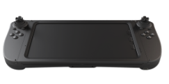
Carrier NAVIGATOR / C-NAVIGATOR & C-ATLAS
Display | 8″ Capacitive touch screen, high-sensitivity |
|---|---|
Resolution | 1280×800 WXGA |
Size (L x W x D) | 308 x 137.8 x 63.75 mm, 953 g |
OS Processor RAM ROM | Android 15 Octa Core, 2.7 GHz 4GB 64GB |
Radio Bandwidth Encryption Compliance | 2×2 MIMO Microhard pMDDL2450; 2.402 – 2.482 GHz 4 / 8 MHz AES IP-68 |
GCS Protocols | MAVLink |
Flight Controls Front Side: Top: | 2 x 2-axis joysticks with built-in buttons, 2 x 1-axis joysticks with built-in buttons, and 12 x additional buttons 2 x push buttons |
Antenna | Omni-directional antenna (9.5dBi) * 2 detachable |
Charging | USB Type–C |
Temp Range | -40 ~ +50 °C |
Resolution | 1920×1200 WUXGA |
Important: Never power a ground control station or aircraft without first attaching all antennas. Doing so could result in damage to the transmitting radio. The C-ATLAS comes provided with two diversity antennas that are used for telemetry. Ensure that both of these antennas are connected to take advantage of the switching functionality of the diversity system.
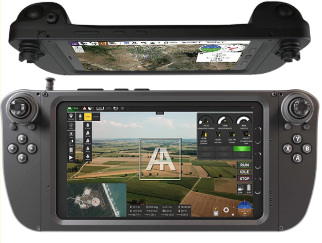
Control Map | Operation |
|---|---|
Control Sticks | The control sticks are used to provide directional control commands to the H6. Its use will be covered in greater detail in a later section. |
YBXA Pads | Y: Loiter Flight Mode; B: Altitude Hold Mode; A: Auto Flight Mode; X: RTL Mode |
Flight Mode Menu | Pop-out menu for flight mode selection |
Plan View | Opens options and settings for mission planning |
Quick Actions | Tab menu for quick actions such as Auto Takeoff, RTL, and other actions |
Generator Information | Tab menu with monitoring for RPM, Throttle %, Current draw, Supplied voltage, Power output, Cylinder head temp, and more. |
Generator State Toggle | Tab menu for switching generator states |
Fuel and Battery Level | Tab menu for monitoring fuel and battery remaining |
Power Button | GCS Power On/Off |
Arrow Pad | Optional: Features to be determined. |
Rear Joysticks | Gimbal Controls |
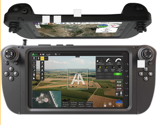
C-NAVIGATOR Powering On Procedures | C-NAVIGATOR Powering Off Procedures |
|---|---|
|
|
C-Navigator Indicator Lights
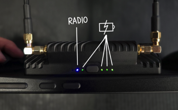
The NavBay on the exterior of the controller includes a series of LEDs that are used to indicate power, battery state-of-charge, and malfunctions.
- The presence of a red LED, on the far left, indicates that there may be a hardware malfunction with the controller. If this occurs, power cycle the controller and NavBay to clear the issue. If the issue persists, please report your findings to support@harrisaerial.com
- The presence of a blue LED, center left, indicates that the NavBay is powered on.
- The remaining LEDs are green, and indicate the state-of-charge for the internal batteries. Note: When the NavBay is toggled into charge mode, these LEDs will flash.
- Four green LEDs = 100%
- Three green LEDs = 75%
- Two green LEDs = 50%
- One green LED = 25%

Connecting To The Aircraft: Troubleshooting (C-Navigator)
CONNECTION TROUBLESHOOTING
- Connection issues are typically related to one or more of the following factors: hardware, software, or interference. In this section we’ll cover possible issues and potential solutions.
- RC Failsafe:
- If an RC failsafe is experienced, specifically when the aircraft has not been flown BVLOS, behind an obstruction, or is close in proximity to your launchsite, there is a possibility that either the antennas, coaxial cables, or radio is damaged and has a weak received signal-strength (RSSI). Allow the vehicle to RTL and once a connection is reestablished, attempt to replicate the issue. Please refer to the “Radios” section on this page for more information about radio troubleshooting.
If an RC failsafe is experienced while the vehicle is at range or BVLOS this may be due to a brief loss of connection. Allow the vehicle to RTL or establish manual control once the vehicle is within VLOS to determine if connection has been reestablished.
- Unable to connect to vehicle:
Make sure the Microhard radio is powered on by checking the radios status LEDs on the Navbay mounted to the rear of the controller (See image). Verify that the Navbay has adequate battery life, and the blue LED is illuminated. If the radio was off, wait some time for the connection to be established.If the battery life LED indicators are low or depleted, but the charger was recently fully charged, please submit a support ticket for further instruction.
Make sure no active Wi-Fi connections are present and turn Wi-Fi off in the Wi-Fi settings page.
If issues persist, open the NAVsuite app on the tablet’s home screen. If the app fails to open and the batteries are fully charged or connection over HAGC or NAVsuite have been intermittent, please submit a support ticket for further instruction.
Loss of Video Stream (FPV):
- If a loss in your first-person view (FPV) camera’s video stream occurs follow the instructions below:
Microhard equipped vehicles use the InVID IP Camera which streams video over ethernet, which is then transmitted to the C-Navigator screen.
- If video streaming is not present, determine if a new version of HAGC has been installed. This could mean the IP address has not been entered into the video streaming settings in “Application Settings → General”. Please see the photo below and verify the IP address has been entered as shown.
- If video streaming issues persist, check the connection of the power/ethernet cable on the rear of the camera – For H6 models, this is mounted beneath the front of the vehicle, for H8 models on top (Note: H8 models camera power cables are not as easily accessible). Next, enter the avionics compartment and trace the cabling to the power distribution board and the radio looking for disconnections or damaged wiring.
- If video streaming issues have not been resolved please submit a support ticket for further instruction or possible replacement.
Power, Display, or other C-Navigator related issues
- Issues such as inability to power on the C-Navigator, loss of display, or other issues that aren’t related to HAGC may require guided support or RMA. Please submit a support ticket for further instruction.
Connecting To The Aircraft: HereLink (Deprecated)
All of our legacy controllers and currently supported models will be featured here.
HereLink, C-ATLAS, C-NAVIGATOR (coming soon), & C-SRoC (coming soon)
Get to know your controllers:


Connecting To The Aircraft: Troubleshooting (HereLink)
CONNECTION TROUBLESHOOTING
- Connection issues are typically related to one or more of the following factors: hardware, software, or interference. In this section we’ll cover possible issues and potential solutions.
- RC Failsafe:
If an RC failsafe is experienced, specifically when the aircraft has not been flown BVLOS, behind an obstruction, or is close in proximity to your launchsite, there is a possibility that either the antennas, coaxial cables, or radio is damaged and has a weak received signal-strength (RSSI). Allow the vehicle to RTL and once a connection is reestablished, attempt to replicate the issue. Please refer to the “Radios” section on this page for more information about radio troubleshooting.
- If an RC failsafe is experienced while the vehicle is at range or BVLOS this may be due to a brief loss of connection. Allow the vehicle to RTL or establish manual control once the vehicle is within VLOS to determine if connection has been reestablished.
- Loss of Video Stream (FPV):
- If a loss in your first-person view (FPV) camera’s video stream occurs, the first step is determine which radio your aircraft is equipped with, Herelink or Microhard.
- Herelink equipped vehicles use a CamPark FPV camera which streams video through a mini HDMI cable. This is then transmitted to a Herelink controller specifically for viewing the video feed.
If video streaming is not present, start by power cycling the CamPark FPV camera and removing the HDMI cable from the side of the camera.
Once the camera has powered back on, remove it from its mount Once the camera has powered back on, remove it from its mount and enter the settings menu – press the menu button on the front until settings appears, navigate through the menu and locate both screen saver and power saver menus, change these to “OFF”. Reinsert the HDMI cable and check your Herelink for video stream. - If video streaming issues persist, check the HDMI channel on HAGC – In the bottom right corner of the screen in HAGC, locate a tiny “cog” and press it. A menu will appear with the options HDMI1 and HDMI2. Make sure the HDMI channel selected matches the HDMI port used on the Herelink air unit. If issues persist, attempt to move the HDMI cable to another port and retry.
- If video streaming has not been resolved, the next step would be to replace either the HDMI cable, FPV camera, or Herelink air unit, in the listed order. Please submit a support ticket for further instruction.
Power, Display, or other C-Navigator related issues
- Issues such as inability to power on the HereLink, loss of display, or other issues that aren’t related to HAGC may require guided support or RMA. Please submit a support ticket for further instruction.
Pre-Flight Checks: For All Carriers & Devices
Ensure you’re getting everything in order prior to flight with our comprehensive checklist:


Submit A Ticket
Contact Information
Drop us a line here and we will get back to you within 24 hours.
- +1-850-800-9103
- support@harrisaerial.com
Radio
Initial Steps & Configurations
All Drone Models
Your Harris Aerial Drones will come equipped with one of the following radio options:

Ensure the following generator, telemetry, & connectivity checks are done regularly – especially after self-maintenance.

C-GCS
RFD900x Radio Troubleshooting:
If connection issues with your RFD900x are suspected, this could be a result of damaged antennae, coaxial cables, or the radio itself. Below are step-by-step instructions designed to troubleshoot the cause of the issue:
- Visual Inspection: Inspect your vehicle and C-GCS to make sure the correct antennae are installed. 900MHz antennae can be identified by their non-anodized aluminum base. If they are installed, remove an antenna and inspect the polarity of the connector within and make sure it is designed to mate with the coaxial cable on the vehicle or C-GCS (e.g. RP-SMA female→RP-SMA male). Check each antenna for damage such as bending or separation of the antenna body
- Avionics Inspection: Remove your fuel tank or battery rack, and unscrew the four screws securing the cover plate in the center of your vehicle. Find the RFD in the bottom left corner of the avionics board, closest to the front of the vehicle. Inspect the coaxial cable connection, polarity, and integrity. Next, find the wiring harness inserted into the back of the radio and trace each wire looking for severed wires or de-pinning. With the vehicle powered on and radios connected (if applicable), observe the LEDs through the small porthole on the top of the assembly. Rapid flashing indicates transmission to and from the radios, if this is blinking green in a slow pattern, this indicates a connection is not present.
- Power Cycling: C-GCS are equipped with a radio killswitch primarily used for power cycling the installed radio(s). If the vehicle is having difficulty establishing a connection prior to takeoff, e.g. “Not Ready”, use this switch to refresh the radio and attempt to connect to the vehicle again.
- RFD Tools Inspection: Using RFD Tools, which is available on your USB drive or through https://rfdx.atlassian.net/servicedesk/customer/portal/1/article/242712577, connect to the associated COM port for your RFD radio with a Baud rate of 57600.
Verify that your settings match those shown in the photo (excluding NET ID)

- For NET ID, this should be programmed to the VIN of your vehicle, found on the vehicle near your GPS stands. H6E###.
- If all the settings match and connectivity issues persists, enter the “Terminal” tab at the top of RFD Tools. In the command prompt, enter “AT&T=RSSI”. This will begin populating an RSSI debug report. Assess the L/R RSSI (local and remote) on the left. With the vehicle in close proximity, ideal RSSI should be 206/206. If RSSI is changing in number over time, this indicates that a component may be damaged. If replacement antennae are readily available, swap one antenna at a time to determine if the issue is resolved.
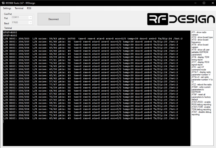
If issues persist after replacing the antennas, inspect the coaxial cables for damage or pin recession. Pin recession can occur on C-GCS when the coaxial cable itself is loose within the C-GCS and spins while attaching antennas.
If coaxial cables or a radio are suspected to be damaged, please submit a ticket for replacement.
Microhard Radio Troubleshooting:
If connection issues with your Microhard radio are suspected, this could be a result of damaged antennae, coaxial cables, or the radio itself. Below are step-by-step instructions designed to troubleshoot the cause of the issue:
- Visual Inspection: Inspect your vehicle and C-GCS to make sure the correct antennae are installed. 2.4GHz antennae can be identified by their distinct trapezoidal shape at the C-GCS and double arrow shape on the vehicle. If they are installed, remove an antenna and inspect the polarity of the connector within and make sure it is designed to mate with the coaxial cable on the vehicle or C-GCS (e.g. RP-SMA female→RP-SMA male). Check each antenna for damage such as bending or separation of the antenna body.
- Avionics Inspection: Remove your fuel tank or battery rack, and unscrew the four screws securing the cover plate in the center of your vehicle. Find the Microhard on the outside rear of the vehicle. Inspect the coaxial cable connection, polarity, and integrity. Next, find the wiring harness inserted into the back of the radio and trace each wire into the avionics bay looking for severed wires or de-pinning. With the vehicle powered on and radios connected (if applicable), observe the LEDs on the top of the assembly. Rapid flashing indicates transmission to and from the radios, if this is blinking green in a slow pattern, this indicates a connection is not present.
- Power Cycling: C-GCS are equipped with a radio killswitch primarily used for power cycling the installed radio(s). If the vehicle is having difficulty establishing a connection prior to takeoff, e.g. “Not Ready”, use this switch to refresh the radio and attempt to connect to the vehicle again. If none of these steps resolve the connectivity issue, advanced steps may be needed. Please submit a ticket for further instruction.
C-Navigator
- Microhard Radio Troubleshooting:
If connection issues with your Microhard radio are suspected, this could be a result of damaged antennae, coaxial cables, or the radio itself. Below are step-by-step instructions designed to troubleshoot the cause of the issue:
- Visual Inspection: Inspect your vehicle and C-Navigator to make sure the correct antennae are installed. 2.4GHz antennae can be identified by their distinct trapezoidal shape at the C-Navigator and double arrow shape on the vehicle. If they are installed, remove an antenna and inspect the polarity of the connector within and make sure it is designed to mate with the coaxial cable on the vehicle or C-Navigator (e.g. RP-SMA female→RP-SMA male). Check each antenna for damage such as bending or separation of the antenna body.
- Avionics Inspection: Remove your fuel tank or battery rack, and unscrew the four screws securing the cover plate in the center of your vehicle. Find the Microhard on the outside rear of the vehicle. Inspect the coaxial cable connection, polarity, and integrity. Next, find the wiring harness inserted into the back of the radio and trace each wire into the avionics bay looking for severed wires or de-pinning. With the vehicle powered on and radios connected (if applicable), observe the LEDs on the top of the assembly. Rapid flashing indicates transmission to and from the radios, if this is blinking green in a slow pattern, this indicates a connection is not present.
- Power Cycling: If the vehicle is having difficulty establishing a connection prior to takeoff, e.g. “Not Ready”, power cycle the controller to refresh the radio and attempt to connect to the vehicle again. If none of these steps resolve the connectivity issue, advanced steps may be needed. Please submit a ticket for further instruction.
Turn off Wi-Fi: Using the C-Navigator as a ground control station while Wi-Fi is enabled severs the link between the radio and the vehicle. If Wi-Fi was used to download maps or perform system updates recently, verify that it is turned off in Wi-Fi settings and auto-reconnect is disabled.
HereLink
If connection issues with your Herelink radio are suspected, this could be a result of damaged antennae, coaxial cables, or the radio itself. Below are step-by-step instructions designed to troubleshoot the cause of the issue:
- Visual Inspection: Inspect your vehicle and Herelink controller to make sure the antennae are installed. Check each antenna for damage such as bending or separation of the antenna body.
- Avionics Inspection: Remove your fuel tank or battery rack, and unscrew the four screws securing the cover plate in the center of your vehicle. Find the Herelink mounted on the outside front of the vehicle. For inspection purposes the Herelink protective cover will need to be removed. Inspect the coaxial cable connection, polarity, and integrity. Next, find the wiring harness inserted into the back of the radio and trace each wire into the avionics bay looking for severed wires or de-pinning. With the vehicle powered on and radios connected (if applicable), observe the LEDs on the side of the assembly. Rapid flashing indicates transmission to and from the radios, if this is blinking green in a slow pattern, this indicates a connection is not present.
- Power Cycling: If the vehicle is having difficulty establishing a connection prior to takeoff, e.g. “Not Ready”, power cycle the controller to refresh the radio and attempt to connect to the vehicle again.
- Pairing: Pull down from the top of the Herelink’s screen, there will be a notification that says “Herelink Settings” and “Radio Status”, click on this to enter the Herelink settings menu. The first menu “RADIO” provides information about Pair State, Signal Strength, and Uplink rate & Bandwidth. Verify that there are values populated and changing here. If no uplink is shown, press the pair button on the controller, and then quickly press and hold the pair button on the air unit until an uplink rate is visible. Sometimes the pairing screen will get stuck in a pending loop. Simply close out of the Herelink settings menu, and re-enter.
- Firmware Version: In the Herelink settings menu, navigate to the “AIRUNIT” tab, and check the “Local” and “Air” version for firmware consistency. This issue will only occur if an update was knowingly performed. If none of these steps resolve the connectivity issue, advanced steps may be needed. Please submit a ticket for further instruction.
Submit A Ticket
Contact Information
Drop us a line here and we will get back to you within 24 hours.
- +1-850-800-9103
- support@harrisaerial.com
Remote ID
Remote ID Troubleshooting
C-GCS
C-GCS Remote ID Troubleshooting
If remote ID issues are resulting in an “Open Drone ID” error in your flight software messages, follow the steps below to attempt to correct the issue.
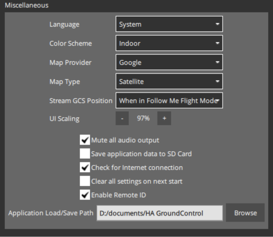
In HA Ground Control, click the HA logo in the top left corner and enter the “Application Settings” menu. Under the General sidebar tab, scroll down until you find the “Miscellaneous” settings. Verify that “Enable Remote ID” is checked.
Next, select the Remote ID sidebar tab, and verify that your settings match the image below. Basic ID should be 18136(vehicle model – H6E or H8E)(VIN). Select the appropriate COM port for your Garmin or GLONASS USB, which can be found in the Windows “Device Manager” under Ports
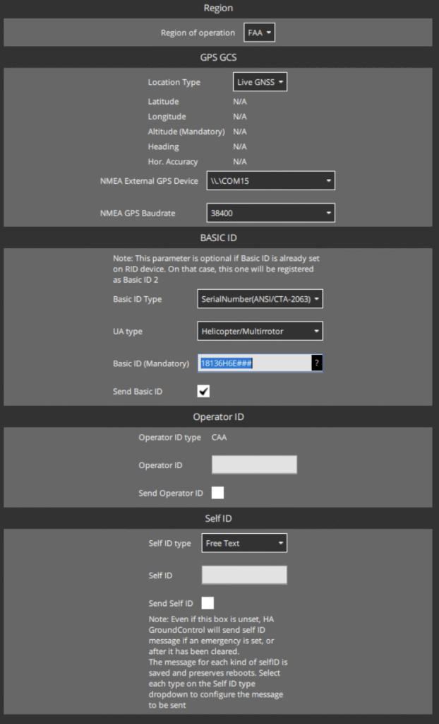
- If issues persist and you’re using a Garmin device, navigate to the Windows Bluetooth devices menu. Find the Garmin GLO 2 device and select “Remove Device”. Once removed, select “Add Bluetooth or other Device”. A pop-up window will appear, select “Bluetooth”. In some cases, the Garmin GLO 2 will appear initially as a set of headphones, otherwise wait for a moment for it to register as a Garmin GLO 2, select the device, and pair. Enter the “Device Manager” and find the new COM ports associated with the device. Garmin GLO 2 will create four COM ports all of which are in sequential order. Once the four COM ports have been identified, attempt to establish connection in HA Ground Control. Note: Two COM ports, when selected, will cause the LEDs on the Garmin to remain solid, one of these will establish the link.
- If none of these steps resolve the connectivity issue, advanced steps may be needed. Please submit a ticket for further instruction.
C-Navigator
C-Navigator Remote ID Troubleshooting
If remote ID issues are resulting in an “Open Drone ID” error in your flight software messages, follow the steps below to attempt to correct the issue.
In HA Ground Control, click the HA logo in the top left corner and enter the “Application Settings” menu. Under the General sidebar tab, scroll down until you find the “Miscellaneous” settings. Verify that “Enable Remote ID” is checked.
Next, select the Remote ID sidebar tab, and verify that your settings match the image below. Basic ID should be 18136(vehicle model – H6E or H8E)(VIN). Disregard the NMEA External GPS Device and Baudrate dropdowns as they are not relevant to the C-Navigator.
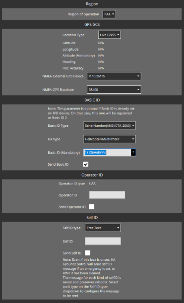
- If issues persist and you’re using a Garmin device, use this document to troubleshoot further: Garmin with Navigator5.pdf
- If none of these steps resolve the connectivity issue, advanced steps may be needed. Please submit a ticket for further instruction.
HereLink
HereLink Remote ID Troubleshooting
- If remote ID issues are resulting in an “Open Drone ID” error in your flight software messages, follow the steps below to attempt to correct the issue.
- First, determine if you’re using the Remote ID function via HA Ground Control or Herelink Settings menu. A quick way to determine if you’re using the Herelink settings Remote ID is to look for an exclamation mark in the bottom right corner of your Herelink’s screen. If this is not visible, you’re using the HA Ground Control remote ID.
If you’d like to use the Remote ID in HA Ground Control, click the HA logo in the top left corner and enter the “Application Settings” menu. Under the General sidebar tab, scroll down until you find the “Miscellaneous” settings. Verify
- First, determine if you’re using the Remote ID function via HA Ground Control or Herelink Settings menu. A quick way to determine if you’re using the Herelink settings Remote ID is to look for an exclamation mark in the bottom right corner of your Herelink’s screen. If this is not visible, you’re using the HA Ground Control remote ID.
Next, select the Remote ID sidebar tab, and verify that your settings match the image below. Basic ID should be 18136(vehicle model – H6E or H8E)(VIN). Disregard the NMEA External GPS Device and Baudrate dropdowns as they are not relevant to the HereLink.
- If you’d like to use the Herelink setting Remote ID first make sure to disable Remote ID in HA Ground Control via the Application Settings menu→General→Miscellaneous, pull down from the top of the Herelink’s screen, there will be a notification that says “Herelink Settings” and “Radio Status”, click on this to enter the Herelink settings menu. Select the Remote ID tab from the top bar. Select the Enable RID slider, enter 18136(H6E or H8E)(VIN) into UAS ID, skip Operator ID (unless needed) and the remaining options. Select “Serial Number” from the first dropdown menu on the right and “Helicopter or Multirotor” from the second dropdown.
Submit A Ticket
Contact Information
Drop us a line here and we will get back to you within 24 hours.
- +1-850-800-9103
- support@harrisaerial.com
Hardware Issues
RFD GCS Connectivity
New Models
Use the toggle power switch on new RFD GCS models.
Older Models
- Remove the power cord from the interior for older models.
RFD Tools Disclaimer
- Do not tamper with RFD tools unless qualified.
Hardware Issues
Connectivity Troubleshooting
Steps 1-7
- Ensure the drone cannot connect from the ‘Plan’ screen.
- Verify that comm cords are correctly connected.
- Ensure RFD settings are correct.
- Power the RFD on and off.
- Verify the correct comm port is selected.
- Ensure the baud rate is set to 57600.
- Contact support for further RFD troubleshooting.
Manufacturer Documentation
For detailed troubleshooting steps and settings, refer to the RFD Tools Documentation and Mission Planner Communication Setup.
Version Update Request
FORM GOES HERE
Hardware issues
Herelink Troubleshooting
Connectivity Issues
- Ensure the Herelink device is properly paired with the UAV.*
- Check for firmware updates and install the latest version.
- Ensure antennas are correctly positioned and not obstructed.
- For detailed setup and troubleshooting, refer to the Herelink User Guides.
For more comprehensive information and step-by-step guides, refer to the Herelink FAQ and Herelink Troubleshooting pages.
Submit A Ticket
Submit A Ticket
Hardware issues
Telemetry Remote ID Trouble Shooting
Connectivity Issues
- If a laptop and carrier link are being used simultaneously with a C-Navigator, Herelink, or other handheld device to monitor telemetry, make sure Remote ID is disabled in the Application Settings→General→”Enable Remote ID” section of HA Ground Control on the laptop.
Submit A Ticket
Contact Information
Drop us a line here and we will get back to you within 24 hours.
- +1-850-800-9103
- support@harrisaerial.com